USB media controller design
Most of us will have a Netflix, Spotify or different kind of media streaming account. Having a small device on your desk to quickly pause, resume skip or rewind your media with a single click can come in handy when taking a quick break without wanting to alt-tab or keep on rewinding that one amazing song effortlessly. Applications playing media can be controlled using Human Interface Devices, HID in short. In some cases this also applies for videos being played from the internet.
To be able to easily control all of our media players, let’s create such a HID!
Processor & IO
To let the media controller talk to a computer, we need to add a microprocessor and ideally a small one to keep the size of our media controller to a minimum. There are multiple ways of creating very small pcbs for this project but one of the easiest ways of prototyping is using an Arduino. The smallest Arduino boards are the Pro Mini, Nano, Pro Micro and the ATtiny modules.
Out of those, I chose the Arduino Pro Micro which is based on the ATmega32u4 microprocessor. It’s the little brother of the Arduino Leonardo board and contains 12 digital input/outputs and a 16MHz clock frequency which is plenty for what we’ll need.
The reason I chose this specific board over other boards is the microprocessor that it is based on: the ATmega32u4. This microprocessor has built-in USB communication, which allows it to be used as a mouse or keyboard. In this project we will let our media controller act as a keyboard to send standardized commands to the computer. This approach makes the media controller easy to use with a variety of different devices. Another benefit of the Pro Micro is its integrated micro-usb port, a cable which many of us have laying around.
Apart from the processor we need a way to get user input: buttons. As shown later on, I chose to give these buttons a form corresponding to their function. This non-standard form factor meant I had to use small switches below the buttons to actually register a click.
To avoid noise impacting the buttons, they were configured as in a pull-up configuration as can be seen in figure 1. Although the Arduino Pro Micro has on-board pull-up resistors which can be enabled through the firmware, I didn’t think of this at the time and used external pull-up resistors with a resistance of 10KΩ.
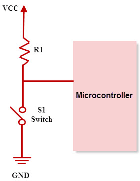
Figure 1: Pull-up resistor. Source: www.elprocus.com/pull-up-and-pull-down-resistors-with-applications
These buttons alongside their pull-up resistors were soldered onto a piece of protoboard which was cut to 35x20mm to be slightly bigger than the Arduino. This board now contained the circuit from figure 1 three times, and was connected to 5 wires:
- All VCC nodes were connected together and soldered to the Arduino using a single wire
- All GND nodes were connected together and soldered to the Arduino using a single wire
- Each of the wires from figure 1 going to the microprocessor was connected to a GPIO
Soldering this all in place finished the design of the protoboard and allowed me to interact with the Arduino
3D design
Having chosen a microprocessor and a way of interacting with the user, it’s time to think about how this is all going to come together. Let’s first make a list of the components that we have to fit into an as small as possible enclosure:
- Arduino Pro Micro
- Protoboard containing the buttons
- Cable connecting the protoboard to the Arduino
- 3 different buttons: play/pause, next and previous track
The easiest way to create such a custom enclosure in which all components will fit is using a 3D printer and CAD software to create a 3D model of the entire device. This 3D model also allows us to significantly reduce the number of iterations required to finalize our enclosure since we get a pretty good guess how things will turn out before even looking at our 3D printer.
In order to design the final enclosure as can be downloaded below, I first made a prototype for the 3D printed buttons. These needed to be easy to press through the lid of the enclosure but could not fall out when the device would be held upside down. This was achieved by giving them small flaps at the bottom and a negative cutout in the lid for these flaps. Apart from the intended locking mechanism, this also provided a stable feel when pressing the button although I had to file down the rough printing edges of the buttons.
Next up was getting the Arduino into the module. Since the Arduino is just slightly smaller than the protoboard, the enclosure could be designed in such a way that the Arduino could be put in the USB connector first at a 30 degree angle and then be pushed into its final position while the supports for the protoboard allowed a stable base for the buttons.
Finally the lid has been designed to snap into the case and provide a screwless connections strong enough to keep everything together but also allow the media controller to be opened when maintenance is required.
Figure 2 shows an exploded view of the final 3D design of the case showing the individually discussed components starting top to bottom:
- case_lid.STL
- arrow.STL + playpause.STL
- The protoboard containing the switches and pull-up system
- The Arduino Pro Micro
- case.STL
Figure 2: Exploded view of the final enclosure design
Firmware
The firmware of the Arduino Pro Micro is responsible for the interaction between the media controller and the device it is connected to. The chosen way of interaction is by using HID commands, which is universally accepted by devices. The available media HID commands with their associated hex codes are:
Playback control:
        MEDIA_RECORD = 0xB2,
        MEDIA_FAST_FORWARD  = 0xB3,
        MEDIA_REWIND  = 0xB4,
        MEDIA_NEXT  = 0xB5,
        MEDIA_PREVIOUS  = 0xB6,
        MEDIA_PREV  = 0xB6,
        MEDIA_STOP  = 0xB7,
        MEDIA_PLAY_PAUSE  = 0xCD,
        MEDIA_PAUSE = 0xB0,

Volume control:
        MEDIA_VOLUME_MUTE = 0xE2,
        MEDIA_VOL_MUTE = 0xE2,
        MEDIA_VOLUME_UP = 0xE9,
        MEDIA_VOL_UP  = 0xE9,
        MEDIA_VOLUME_DOWN = 0xEA,
        MEDIA_VOL_DOWN  = 0xEA,
The firmware used on the current version of the media controller implements three of those commands:
- MEDIA_PLAY_PAUSE
- MEDIA_NEXT
- MEDIA_PREV
These aliases can be used directly since they are declared as a constant in the HID-project library. All available aliases for the consumer class can be found here: https://github.com/NicoHood/HID/blob/master/src/HID-APIs/ConsumerAPI.h
To prevent sending multiple commands when clicking a button once, a debounce time of 20 ms is added which resets if a button is pressed again within this time period.
#include <HID-Project.h>
#include <HID-Settings.h>

// pins to which the buttons are connected
const uint8_t previous = 14;
const uint8_t play = 16;
const uint8_t next = 10;

// debounce and timer initiated
const uint8_t debounce_time = 20;
uint8_t debounce;  // debounce functions as 8 bits to store 8 individual boolean values
uint32_t timer0 = 0;
uint32_t timer1 = 0;
uint32_t timer2 = 0;
uint32_t curTime;

void setup() {
  Serial.begin(9600);
  Consumer.begin();
  pinMode(previous, INPUT);
  pinMode(play, INPUT);
  pinMode(next, INPUT);
  pinMode(LED_BUILTIN,OUTPUT);
  digitalWrite(LED_BUILTIN,LOW);

}

void loop() {
  // check previous button
  if (!digitalRead(previous) && !bitRead(debounce, 2)) {  // pull-up button -> digitalread = FALSE if pressed
    debounce |= B00000100;           // set debounce flag
    Consumer.write(MEDIA_PREVIOUS);
  }
  else if (digitalRead(previous) && bitRead(debounce, 2)) { // ignore next press but reset timer
    timer2 = millis();
  }

  // check play/pause button
  if (!digitalRead(play) && !bitRead(debounce, 1)) {
    debounce |= B00000010;
    Consumer.write(MEDIA_PLAY_PAUSE);
  }
  else if (digitalRead(play) && bitRead(debounce, 1)) {
    timer1 = millis();
  }

  // check next button
  if (!digitalRead(next) && !bitRead(debounce, 0)) {
    debounce |= B00000001;
    Consumer.write(MEDIA_NEXT);
  }
  else if (digitalRead(next) && bitRead(debounce, 0)) {
    timer0 = millis();
  }

  curTime = millis();  // set current time to check debounce of buttons


  // check if any debounce flags are set
  if (bitRead(debounce, 0) || bitRead(debounce, 1) || bitRead(debounce, 2)) {

    // check which flag is set and if debounce_time since the last button press has elapsed, if so: clear flag
    if (curTime - timer0 >= debounce_time && timer0!=0) {
      debounce &= B11111110;
      timer0 = 0;
    }
    if (curTime - timer1 >= debounce_time && timer1!=0) {
      debounce &= B11111101;
      timer1 = 0;
    }
    if (curTime - timer2 >= debounce_time && timer2!=0) {
      debounce &= B11111011;
      timer2 = 0;
    }
  }
}
Assembly and results
With all parts 3D printed and soldered in place, it is time for the final assembly. Figure 2 shows the order of the components in the case and will function as a guideline.
Step 1
Solder the 5 wires from the protoboard to the Arduino: 1 wire to the 3.3V, 1 wire to the ground and 1 wire to each of the GPIO pins you’d like to read the buttons on. Connect the Arduino to a computer or other playback device to check if everything is connected properly.
Step 2
Insert the Arduino at a 30 degree angle into the case, aiming the USB connector through the slot. The Arduino can now be laid flat on the bottom of the case. See figure 3 for reference.
Figure 3: Final assembly - Arduino inserted
Step 3
Lay the protoboard on top of the supports near the top of the case, see figure 4.
Figure 4: Final assembly - Only the lid is yet to be put in place
Step 4
Insert the printed arrows and play/pause button into the lid and place the lid assembly onto the case, gently push to lock the lid in place.
Step 5
Press the buttons to verify everything works, a green LED should light up when the button is pressed to indicate data is being send to the computer.
Step 6
Done! Congratulations you’ve created an USB media controller!
Demo
- assembly sketch.png
- no_lid.jpg
- no_btns.jpg
- demo.mp4
- media controller STL.zip